
SpaceFrame
Grasshopper Tool
Fall, 2018

The spaceFrame script is a tool that allows users to rapidly produce spatial frames generated from a set of XYZ point coordinates and specific input data to create three dimensional volumes. Combining the computing of Grasshopper, mesh generation of Monolith, and 3D printing technologies allows the production of custom point specific structural nodes for joining multiple frame members.

Grasshopper Logic

Clustered Grasshopper tool
Point Configuration
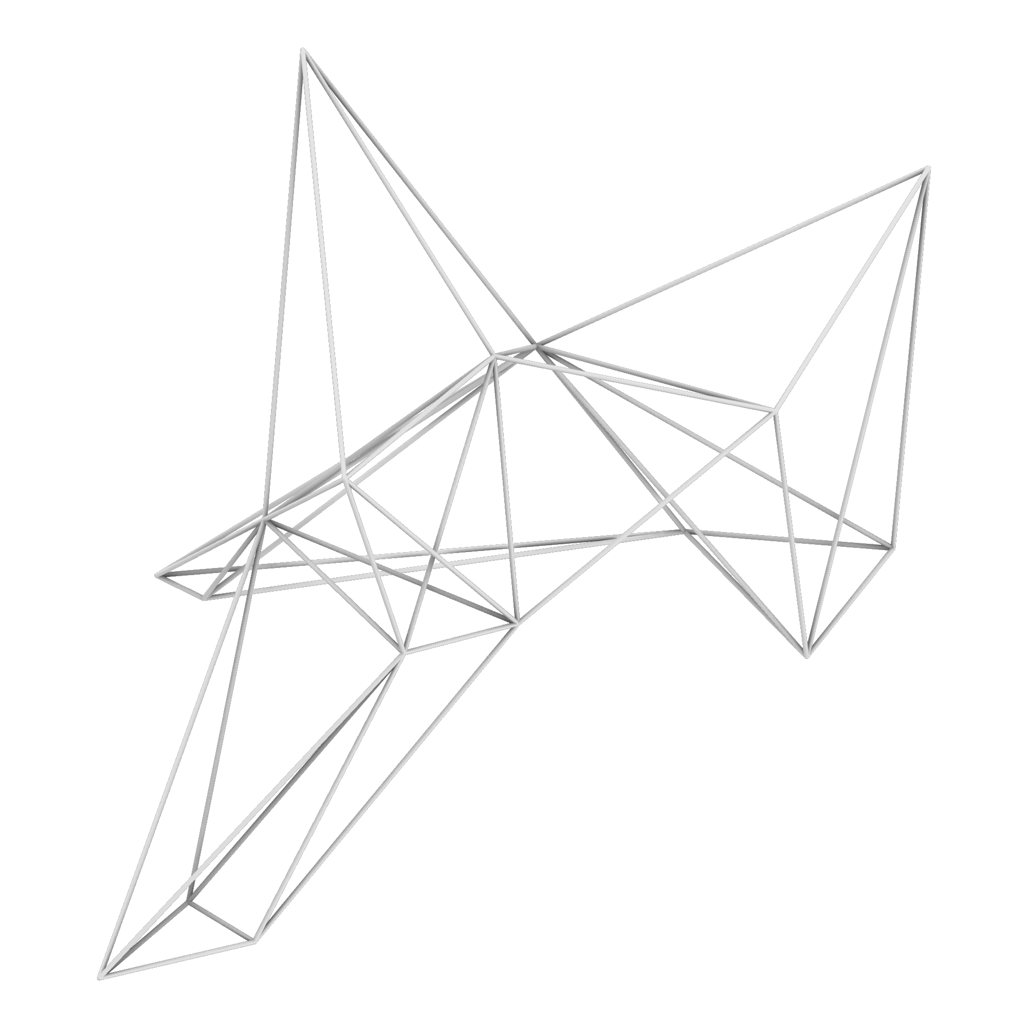
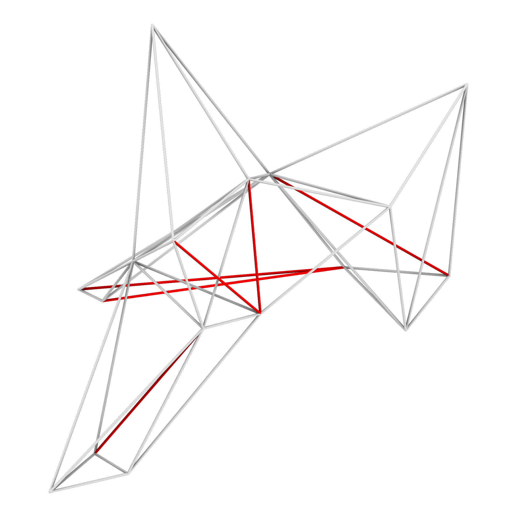
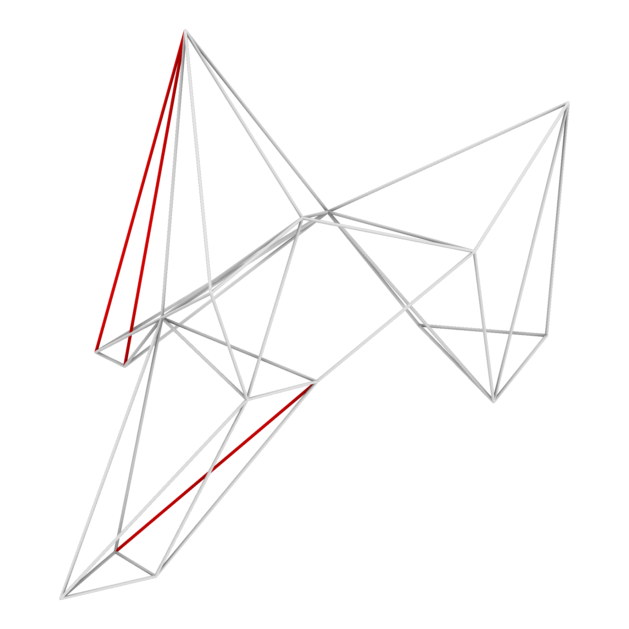
Point XYZ data can be generated through any process as long as the data can be imported into Grasshopper (Rhinoceros generation, motion point detection, excel spread sheets, etc.). Once coordinate data has been imported into Grasshopper, the distance between each point is determined a line is constructed between each point and a user defined number of closest points.


Members Per Node
Grasshopper will sort the distance between each point and every other point in the data collection. Defining the number of frame members per node does not guarantee that is the final number of members at each node. A point may be within the list of closest points of multiple nodes resulting in variation of the number of frame members connecting each node. As currently defined, interior nodes tend to have greater complexity compared to nodes at the outer limits of the frame volume. The images below depict frames with a minimum of three, four, and five frame members per node.


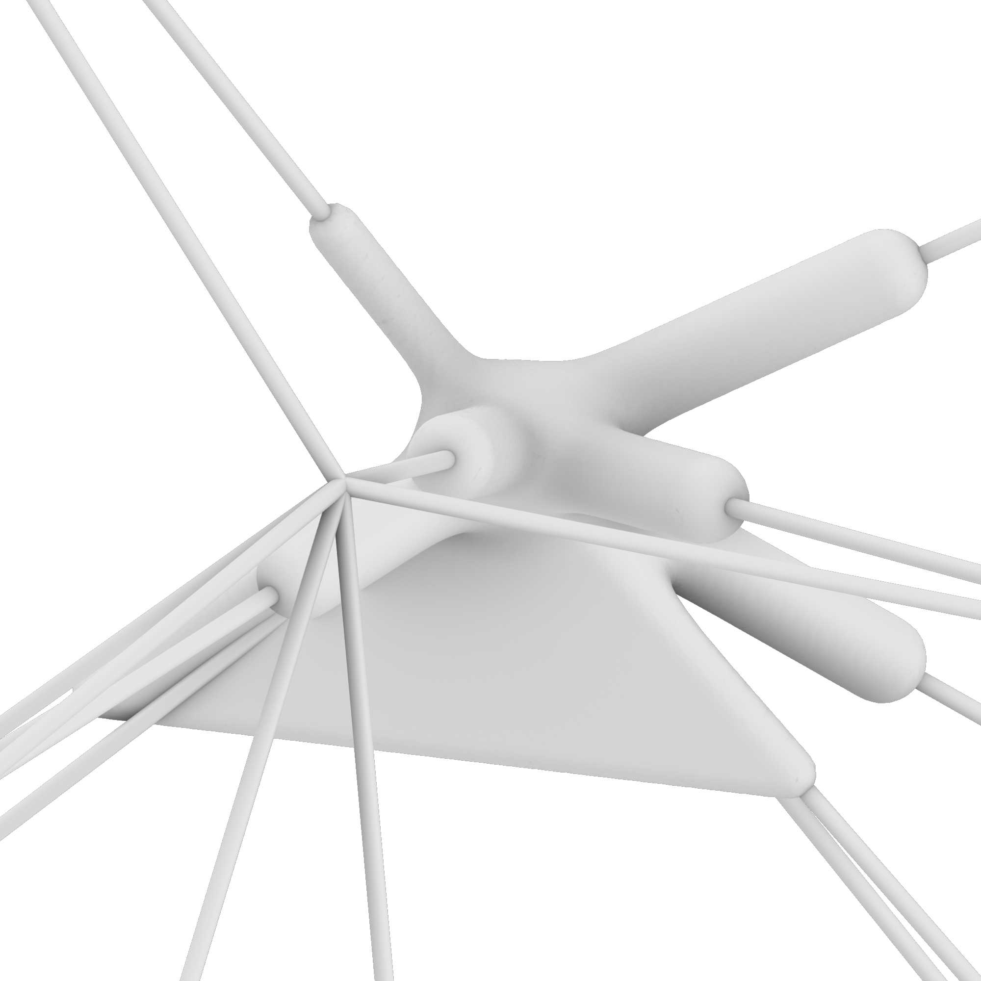


Node Sizing
The dimensions of each node are defined by a box. This box is used for both trimming the frame vectors to the desired lengths as well as providing a voxel field for mesh generation within the Monolith plugin. All curves in the frame are tested to determine if they have an end point at the node being developed. If false they are culled from the list, if true they are split by a user defined box centered at each node. The split curves are tested again to determine if they are inside of the node box; if false they are culled from the list, if true they are used to generate the input data for Monolith.


Surface Variation Within Nodes
Users can define both a number of surface connecting the node curves as well as a seed value to generate different surface configurations. This can be used structurally, aesthetically, or as a surface for placing AR markers to display additional frame information.


Monolith Values
Monolith converts zero-thickness input geometry such as surfaces, vectors, and points to thickened meshes. This is achieved by dividing a box volume into a 3D grid representing voxels. A voxel field is generated around the zero-thickness geometry which is later used to generate a mesh surface. Geometry near the bounds of the voxel field result in flat meshes whereas geometry kept away from the bounds of the voxel field produce rounded meshes.
Within the Monolith plugin, input values determine the thickness of the mesh being developed. Two of the primary input values are “strength” and “decay”. Strength defines the distance away from the zero-thickness data voxel data is activated and decay determines the rate at which that data begins to be culled. Negative values can create voids in the voxel field if desired.
Similar to strength, “iso value” is the final input defining the thickness of the voxel-based mesh created by Monolith. Larger values activate less of the voxel field while smaller values activate more of the voxel field. Multiple values can be used to create multiple meshes representing the same input geometry; this can be helpful if creating a thickened “shell”.
Strength Manipulation:


Decay Manipulation:


Iso Value Manipulation:


Future Development
Currently these frames can not be assembled with rigid frame members; the complexity of each node quickly creates impossible assembly scenarios. This issue can be resolved through manual boolean operations at each insertion point though that is extremely time consuming. A logical next step for the evolution of this process would be to develop a script to automate a series of boolean operations that create removable clips at each insertion point. These clips would allow frame members to be inserted laterally into two nodes simultaneously; the clips would then be replaced to secure the frame member in place. Another process that would greatly improve this process is the addition of a structural analysis plugin for frame modification. The ability to test each member for redundancy and determine where additional structure is required would not only optimize material usage but also allow this process to be applied to a greater range of scenarios.
Hypothetical Clips:


Hypothetical Removal and Addition of Structural Members:
Hypothetical Use Cases
Multi-Machine Production
Multi-machine production protocols could also developed using this spatial frame production script as a base. 3D printed nodes could be transferred to a team of robotic arms and cataloged through image recognition procedures. QR codes applied to node surfaces can provide assembly procedures and frame member length data generated in Grasshopper for each node. Each member can subsequently be cut to length and placed in the appropriate position by the team of robotic arms.
Structural Volumes From Motion Captured Data
The Spatial Futures Lab at the Georgia Tech College of Design has recently set up a motion capture system using technology from OptiTrack and have developed an interface that allow the point data to be recorded in Grasshopper. This spatial frame script is ideal for further developing the possible uses of the OptiTrack system. Multiple scenarios can be tested, such as developing site specific scaffolding or structural framing in physical space. This could be helpful for designing structures in remote areas by recording frame node coordinates remotely through tracking drone movement.
One could also combine AR modeling environments with the OptiTrack system by placing motion capture tracking points on AR controls. This would allow rapid production of physical frames designed within the AR environment by transferring node coordinates in real-time to Grasshopper.
Temporary Structural Scaffolding for Thin Shell Concrete Structures
This system of spatial definition can be used to create temporary structural scaffolding delivered as a kit of parts to quickly erect custom structures in remote areas. These scaffolds can be combined with traditional construction practices such as ferrocement construction in which an armature is wrapped in layers of mesh (typically steel) and is then covered in thin layers of cement. The mesh reinforces the cement and allows for very thin, strong structures to be quickly erected.
Scaffolding can be produced without ever visiting a site by remotely gathering point coordinates and producing the node geometries and frame members in a controlled off site environment. The frame and construction materials can then be deployed and assembled on site. After assembly, the frames can be wrapped in mesh, covered in cement, and allowed to harden. Finally, the frames can be removed and reassembled to quickly produce multiple structures. Strategies for ensuring the frame does not bond to the cement would need to be explored if multiple repeating structures was the desired outcome.