
Nimbus - Perforated Panels
Formations Studio
Grasshopper Script and Prototyping
Completed Winter, 2018

Nimbus, photo by Formations Studio

Nimbus, photo by Formations Studio
Nimbus gives a sense of destination to the intersection of two prominent axis of downtown, Minneapolis. Constructed of corten steel, it is beautiful and visually awe-inspiring during the day, but during the night it presents its self in a whole new light as light as the interior glows, creating a halo of light hovering in the sky. The sculptural cantilever is designed like an airplane wing, pushing 45 feet over the sidewalk to define the upper bounds of a public theater in a prominent pedestrian area.
For this project I was I was the primary author of the Grasshopper script that was used to generate the cut files for the 100 unique perforated panel faces and 200 unique structural ribs. I also worked with the fabrication team prototyping multiple versions of the panel assemblies that make up the bottom skin of the project.
Each assembly consists of two ribs and a perforated face plate. The perforations are decorative but also serve as the access to the mounting hardware. The ribs not only serve as the panel structure and mounting location but are also used to form each panel. The left and right rib of each assembly have different curvatures giving the illusion of double curvature when the perforated panel is wrapped around them.
The Grasshopper script works be first selecting the panels you would like to produce. The base geometry was modeled by hand though the final production panels are heavily modified.


The panels are first reduced the their final production size. This is to account for an overhang on the upper structure and a slight reveal between each panel. .

After he panel has been trimmed to production size, the panel is temporarily trimmed to the bounds of the perforation pattern. This is based clearance space for the LED lighting and an additional zone for light dispersion.

The perforation area is divided into sub-surfaces.

The the center of the sub-surfaces are populated with a unique pattern for each panel. The pattern acts as a gradient, fading into the solid mass of the upper structure. The length of the panel defines the rate at which the gradient dissolves such that larger panels have a greater area of high-density perforations versus the shorter panels.

The curves generated from the sub-surface pattern are projected onto the production panel and subsequently act as guides to trim the final perforation pattern for each panel.
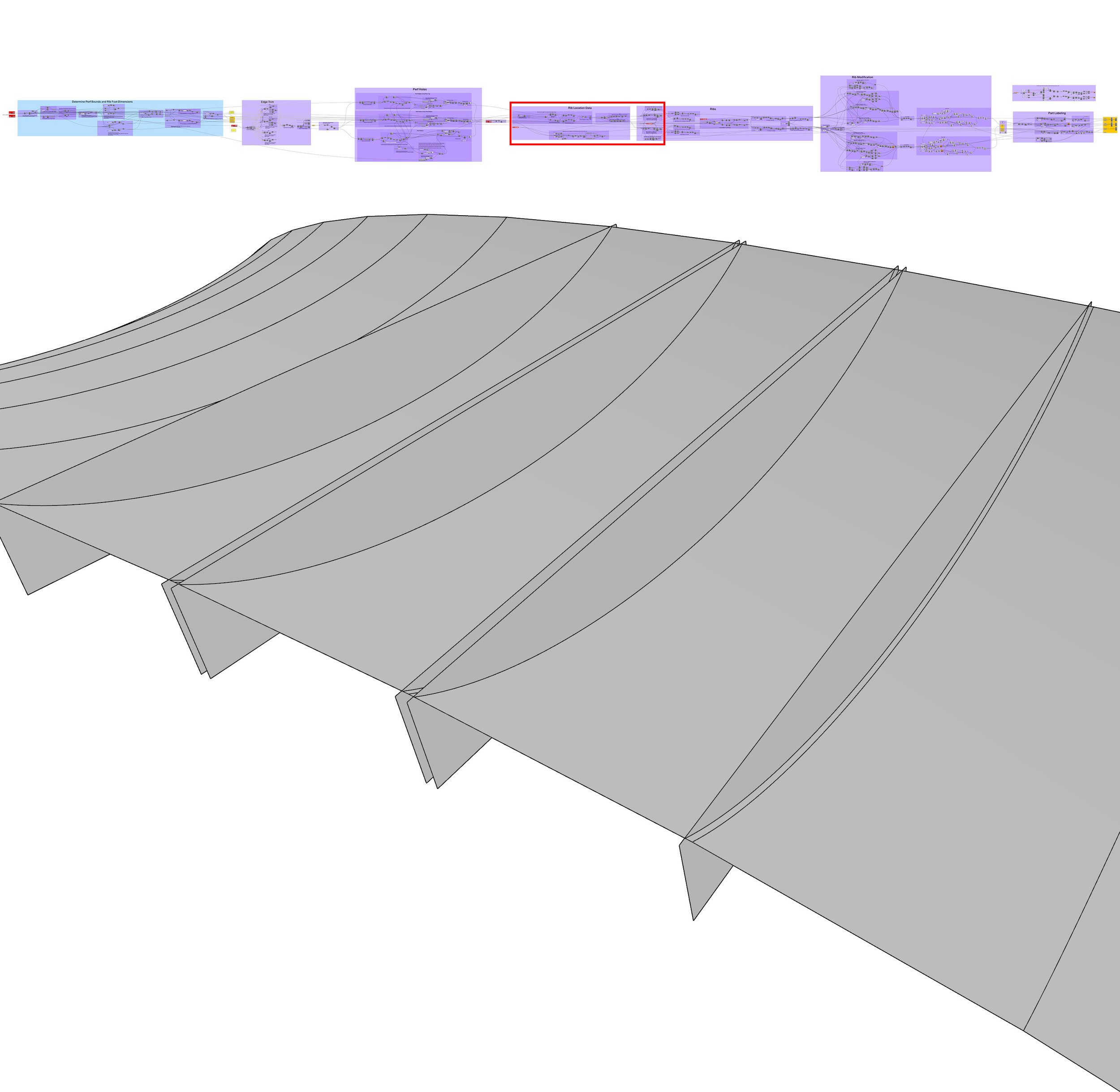
Panel rib placement is determined via defining a surface UV line at the midpoint between the the outside panel edge and the tangent point of the outside-most perforation hole. A surface is generated using data from that line.

The rectangular surface is trimmed for various production and performance criteria. The middle of each rib is removed to allow light dispersion between panels, the tails are removed to allow the end of each panel to have freedom to account for construction tolerances, and various clamping and welding access points are provided.
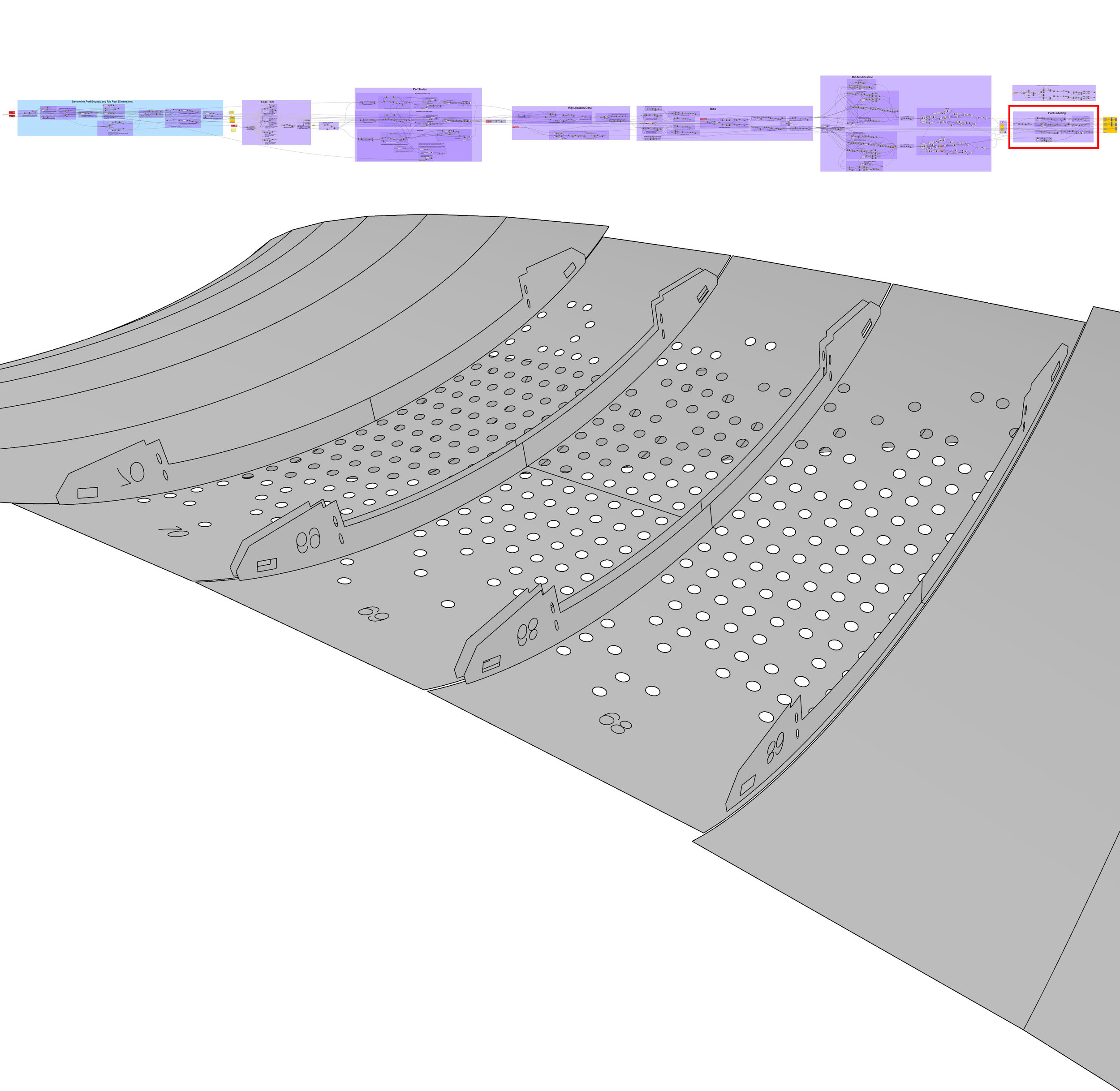
Each panel and rib set is labeled to indicate sets as well as part orientation. Mid points are are also etched to provide production guides.


Finally the parts are unrolled manually and nested onto 5’x10’ sheets for laser cutting.

In house laser cutting saved time and money and allowed us to prototype in real time as design changes were made.

The mid point of each rib are aligned and tack welded to the mid point of each panel. From there the legs of each rib are tacked to the upper structure. Straps and clamps form each panel to the shape of the rib. The final assembly is tacked along each rib. The legs of the final assembly are cut free and the final welds are placed on the interior of each rib.


After each assembly is removed, mounting nuts are fully welded to upper structure. Plates reinforce where the top of each panel bears against the upper structure when fully tightened into place.

Prior to shipping, the LED strands were fitted and test lit on each section.

The piece was assembled off site and dropped into place with the structure fully assembled.

After the piece was mounted to the footer, the LEDs were installed and finally the perf panels were installed.